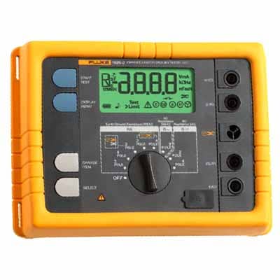
Fluke 1625-2 GEO Earth Ground Tester
Precision grounding tests made simple and reliable
Product Overview
Fluke 1625-2 GEO Earth Ground Tester Price in Bangladesh
Fluke 1625-2 GEO Earth Ground Tester is a professional electrical testing instrument designed for accurate earth resistance measurement, and the keyword Fluke 1625-2 GEO Earth Ground Tester Price in Bangladesh is commonly searched by engineers and electrical contractors who need reliable grounding analysis for industrial and utility systems. It is widely used in substations, power plants, telecom towers, and large electrical installations where safety and accuracy are critical.
This advanced tester supports multiple measurement methods including 3-pole, 4-pole, selective testing, and stakeless (clamp) testing. The stakeless method is especially useful in urban or complex environments where driving ground rods is not practical. This flexibility makes it a highly efficient solution for modern grounding diagnostics.
The device includes Automatic Frequency Control technology, which helps reduce electrical interference from surrounding systems, ensuring more stable and accurate readings. It also features R* measurement capability, providing precise impedance results for better analysis of grounding conditions. These features make it suitable for professional-grade electrical inspections.
The Fluke 1625-2 is designed for field durability and long-term performance. It comes with a rugged protective housing that can withstand harsh outdoor environments, dust, and rough handling. Its intuitive interface allows users to perform tests quickly, even in demanding job site conditions, improving productivity and reducing setup time.
Another key feature is its internal memory, which can store a large number of test results. This allows engineers to review, compare, and document grounding performance over time. Data can also be transferred for reporting and compliance documentation, making it highly useful for maintenance records and safety audits.
Overall, the Fluke 1625-2 GEO Earth Ground Tester stands out as a reliable and advanced solution for earth resistance testing. Its combination of precision, multiple testing modes, and rugged design makes it an essential tool for professionals who require accurate grounding analysis and long-term electrical system safety.
Key features of Fluke 1625-2 GEO earth ground tester
- A unique earth ground tester that performs testing with and without stakes
- Tests 3- and 4-pole fall-of-potential, and 4-pole soil resistivity (with stakes)
- Features Automatic Frequency Control (AFC) to minimize the effect of interference
- Performs stakeless earth ground rod testing (two clamps)
- Performs selective earth ground rod testing (one clamp + stakes)
Specifications
Specifications: Fluke 1625-2 GEO Earth Ground Tester Kit
| General Specifications | |||||
| Memory | Internal memory storage up to 1500 records accessible via USB port | ||||
| Measuring function | Interference voltage and frequency, earthing resistance 3- and 4-pole with/without clip-on current transformer, resistance 2-pole with AC, 2- and 4-pole with DC | ||||
| Display | 4 digit (2999 Digit) - 7 segment liquid crystal display, with improved visibility | ||||
| Operation | Central rotary switch and function keys | ||||
| Temperature Range | |||||
| Operating temperature | -10°C to 50°C (14°F to 122°F) | ||||
| Storage temperature | -30°C to 60°C (-22°F to 140°F) | ||||
| Temperature coefficient | ±0.1% of reading/°C < 18°C > 28°C | ||||
| Type of protection | IP56 for case, IP40 for battery door according to EN60529 | ||||
| Max voltage | Warning – socket "clamp" to socket E, ES, S or H | ||||
| Urms = 0 V | |||||
| Sockets E, ES, S or H to each other in any combination, max. Urms = 250 V (pertains to misuse) | |||||
| Safety | Protection by double and/or reinforced insulation. Max. 50 V to earth per IEC61010-1. Pollution degree 2 | ||||
| Quality standard | Developed, designed and manufactured to comply with DIN ISO 9001 | ||||
| External field influence | Complies with DIN 43780 (8/76) | ||||
| Auxiliary power | 6 x 1.5 V alkaline (IEC LR6 or type AA) | ||||
| Battery life span | With IEC LR6/type AA: typ. 3,000 measurements (RE+RH ≤ 1 kΩ) | ||||
| With IEC LR6/type AA: typ. 6,000 measurements (RE + RH > 10 kΩ) | |||||
| Dimensions (W x H x D) | 250 x 133 x 187 mm (9.75 x 5.25 x 7.35 in) | ||||
| Weight | ≤ 1.1 kg (2.43 lb) without accessories 7.6 kg (16.8 lb) incl. accessories and batteries in carrying case | ||||
| Case material | Polyester | ||||
| Measurement of Interference Voltage DC + AC (UST) | |||||
| Measuring limits of error: method | Full wave rectification | ||||
| Measuring range | 1 V to 50 V | ||||
| Display range | 0.0 V to 50 V | ||||
| Resolution | 0.1 V | ||||
| Frequency range | DC/AC 45 Hz to 400 Hz sine | ||||
| Accuracy | ±(5% of rdg + 5 digit) | ||||
| Measuring sequence | Approx. 4 measurements/s | ||||
| Internal resistance | Approx. 1.5 MΩ | ||||
| Max. overload | Urms = 250 V | ||||
| Measurement of Interference Frequency (F) | |||||
| Measuring limits of error: method | Measurement of oscillation period of the interference voltage | ||||
| Measuring range | 6.0 Hz to 400 Hz | ||||
| Display range | 16.0 Hz to 299.9 Hz to 999 Hz | ||||
| Resolution | 0.1 Hz to 1 Hz | ||||
| Range | 1 V to 50 V | ||||
| Accuracy | ±(1% of rdg + 2 digit) | ||||
| Earthing Resistance (RE) | |||||
| Measuring method | Current and voltage measurement with probe as IEC61557-5 | ||||
| Open circuit voltage | 20/48 V, AC | ||||
| Short circuit current | 250 mA AC | ||||
| Measuring frequency | 94, 105, 111, 128 Hz selected manually or automatic. (AFC) 55 Hz in function R1 | ||||
| Noise rejection | 120 dB (16 2/3 , 50 , 60, 400 Hz) | ||||
| Max. overload | Urms = 250 V | ||||
| Electrical Measurement Specifications | |||||
| Intrinsic Error or Influence Quantity | Reference Conditions or Specified Operating Range | Designation Code | Requirements or Test in Accordance with the Relevant Parts of IEC 1557 | Type of Test | |
| Intrinsic error | Reference conditions | A | Part 5, 6.1 | R | |
| Position | Reference position ±90° | E1 | Part 1, 4.2 | R | |
| Supply voltage | At the limits stated by the manufacturer | E2 | Part 1, 4.2, 4.3 | R | |
| Temperature | 0°C and 35°C | E3 | Part 1, 4.2 | T | |
| Series interference voltage | See 4.2 and 4.3 | E4 | Part 5, 4.2, 4.3 | T | |
| Resistance of the probes and auxiliary earth electrodes | 0 to 100 x RA but ≤ 50 kΩ | E5 | Part 5, 4.3 | T | |
| System frequency | 99% to 101% of the nominal frequency | E7 | Part 5, 4.3 | T | |
| System voltage | 85% to 110% of the nominal voltage | E8 | Part 5, 4.3 | T | |
| Operating error | B = ±(|A| + 1,15 √E21 E22 E23 E24 E25E26 ) | Part 5, 4.3 | R | ||
| B[%] = ± B/fiducial value x 100% A = intrinsic error En = variations R = routine test T = type test |
|||||
| Measuring range | 0.020 Ω to 300 kΩ | ||||
| Display range | 0.001 Ω to 2.999 Ω | ||||
| 3.00 Ω to 29.99 Ω | |||||
| 30.0 Ω to 299.9 Ω | |||||
| 0.300 kΩ to 2.999 kΩ | |||||
| 3.00 kΩ to 29.99 kΩ | |||||
| 30.0 kΩ to 299.9 kΩ | |||||
| Resolution | 0.001 Ω | ||||
| 0.01 Ω | |||||
| 0.1 Ω | |||||
| 1 Ω | |||||
| 10 Ω | |||||
| 100 Ω | |||||
| Accuracy | ±(2% of rdg + 2 digit) | ||||
| Operating error | ±(5% of rdg + 5 digit) | ||||
| Measuring time | Typical 8 seconds with a fixed frequency 30 sec. max. with AFC and complete cycle of all measuring frequencies | ||||
| Additional error because of probe-and auxiliary earth electrode resistance | RH(RS + 2000 Ω)/RE x 1.25 x 10⁻⁶% + 5 digits | ||||
| Measuring error of RH and RS | Typ. 10% of RE + RS + RH | ||||
| Max. probe resistance | ≤ 1 MΩ | ||||
| Max. auxiliary earth electrode resistance | ≤ 1 MΩ | ||||
| Automatic check if error is kept within the limits required by IEC61557-5. If after a measurement of probe-, auxiliary earth electrode- and earthing resistance, a measurement error of higher than 30% is assumed because of the influencing conditions, the display shows a warning symbol and a notice that RS or RH are too high. |
|||||
| Automatic Switchover of Measuring Resolution in Dependence to Auxiliary Earth Electrode Resistance RH | |||||
| RH with Umeas = 48 V | < 300 Ω | ||||
| < 6 Ω | |||||
| < 60 Ω | |||||
| < 600 Ω | |||||
| RH with Umeas = 20 V | < 250 Ω | ||||
| < 2.5 kΩ | |||||
| < 25 kΩ | |||||
| < 250 kΩ | |||||
| Resolution | 1 mΩ | ||||
| 10 mΩ | |||||
| 100 mΩ | |||||
| 1 Ω | |||||
| Selective Measurement of the Earthing Resistance (RE Clamp) | |||||
| Measuring method | Current and voltage measurement with probe as per EN61557-5 and current measurement in the individual branch with additional current transformer (patent applied for). | ||||
| Open circuit voltage | 20/48 V AC | ||||
| Short circuit current | 250 mA AC | ||||
| Measuring frequency | 94, 105, 111, 128 Hz selected manually or automatically (AFC), 55 Hz (R1) | ||||
| Noise rejection | 120 dB (162/3, 50, 60, 400 Hz) | ||||
| Max. overload | Max. Urms = 250 V (measurement will not be started) | ||||
| Measuring range | 0.020 Ω to 300 kΩ | ||||
| Display range | 0.001 Ω to 2.999 Ω | ||||
| 3.00 Ω to 29.99 Ω | |||||
| 30.0 Ω to 299.9 Ω | |||||
| 0.300 kΩ to 2.999 kΩ | |||||
| 3.00 kΩ to 29.99 kΩ | |||||
| Resolution | 0.001 Ω | ||||
| 0.01 Ω | |||||
| 0.1 Ω | |||||
| 1 Ω | |||||
| 10 Ω | |||||
| Accuracy | ±(7% of rdg + 2 digit) | ||||
| Operating error | ±(10% of rdg + 5 digit) | ||||
| Additional error because of probe- and auxiliary earth typ. electrode resistance | RH(RS + 2000 Ω)/RETOTAL x 1.25 x 10⁻⁶% + 5 digits | ||||
| Measuring error of RH and RS | Typ. of 10% of RETOTAL + RS + RH | ||||
| Measuring time | Typ. 8 sec. with a fixed frequency 30 sec. max. with AFC and complete cycle of all measuring frequencies. | ||||
| Minimal current in single branch to be measured | 0.5 mA | With transformer (1000:1) | |||
| 0.1 mA | With transformer (200:1) | ||||
| Max. interference current through transformer | 3 A | With transformer (1000:1) | |||
| 1. With recommended current clamps/transformers. | |||||
| Resistance Measurement (R~) | |||||
| Measuring method | Current and voltage measurement | ||||
| Measuring voltage | 20 V AC, square pulse | ||||
| Short circuit current | > 250 mA AC | ||||
| Measuring frequency | 94, 105, 111, 128 Hz selected manually or automatically (AFC) | ||||
| Measuring range | 0.020 Ω to 300 kΩ | ||||
| Display range | 0.001 Ω to 2.999 Ω | ||||
| 3.00 Ω to 29.99 Ω | |||||
| 30.0 Ω to 299.9 Ω | |||||
| 300 Ω to 2999 Ω | |||||
| 3.00 kΩ to 29.99 kΩ | |||||
| 30.0 kΩ to 299.9 kΩ | |||||
| Resolution | 0.001 Ω | ||||
| 0.01 Ω | |||||
| 0.1 Ω | |||||
| 1 Ω | |||||
| 10 Ω | |||||
| 100 Ω | |||||
| Accuracy | ±(2% of rdg + 2 digit) | ||||
| Operating error | ±(5% of rdg + 5 digit) | ||||
| Measuring time | Typical 6 seconds | ||||
| Max. interference voltage | 24 V, with higher voltages measurement will not be started | ||||
| Max overload | Urms max. = 250 V | ||||
| Resistance Measurement (R DC) | |||||
| Measuring method | Current- voltage measurement as per IEC61557-4 possible | ||||
| Measuring voltage | 20 V DC | ||||
Short circuit
Models: Fluke 1625-2 GEO Earth Ground TesterIncludes:
Accessories: Fluke 1625-2 GEO Earth Ground TesterKits (2)
Cables (3)
Current clamps (1)
Other (3)
Write a ReviewYour Rating |
|||||